Grumman F3F Biplane Scale Model
1:10 SCALE, DESIGNED IN CATIA, CUT FROM PLYWOOD
Overview
This report covers the design, fabrication and testing of a scale model of the Grumman F3F biplane, which we built for the Aircraft Manufacturing Process course in sixth semester. The F3F was the last biplane fighter delivered to the United States Navy, and it is easy to recognize by its barrel-shaped fuselage, radial engine and double-wing layout. We chose it because of its unusual aerodynamic challenges and the manufacturing complexity that comes with a biplane.
We made a 1:10 scale model that keeps the design characteristics of the original while adapting the structure for model construction. The work covered preliminary design, detailed design and analysis, material selection, manufacturing and testing. The model was designed in CATIA V5, analyzed in XFLR5, cut on a laser cutter and assembled by hand as a plywood airframe.
Preliminary Design
The design started by scaling the full-size aircraft by 1:10, with every dimension reduced in proportion. During scaling we paid special attention to the biplane layout, which meant keeping the original stagger (the horizontal offset between the upper and lower wings) and the gap (the vertical distance between the wings). The barrel-shaped fuselage and rounded engine cowling were preserved to keep the look and aerodynamic character of the aircraft.
- Length: 7.32 m full scale, 0.73 m (73 cm) at 1:10
- Upper wingspan: 9.75 m full scale, 0.98 m (98 cm) at 1:10
- Lower wingspan: 9.14 m full scale, 0.91 m (91 cm) at 1:10
- Height: 3.02 m full scale, 0.30 m (30 cm) at 1:10
- Wing area: 24.15 m² full scale, 0.24 m² at 1:10
Design Considerations
Material. Plywood was used for the fuselage, the wing spars and parts of the landing gear.
Airfoil. The upper wing uses NACA 2214, and the lower wing uses a slightly modified NACA 2214 with reduced camber, both compatible with the aerodynamic profile of the original F3F. The section was picked for its well-documented performance at low Reynolds numbers and its relatively flat bottom surface, which makes construction simpler.
Dihedral. The lower wing has 2 degrees of dihedral and the upper wing has none, the same as the original design.
Biplane configuration. The upper wing sits forward of the lower wing (positive stagger), and N-struts and cross bracing hold the wings together and keep the structure rigid.
Center of gravity. The CG is placed at about 25% of the mean aerodynamic chord (MAC) of the lower wing.
Planning. The project was planned over 13 weeks: research and preliminary design, detailed design and CAD modeling, parts preparation and laser cutting, assembly of the main structures, covering and finishing, testing and adjustments, and final documentation.
Detailed Design
The design used XFLR5 for the aerodynamic analysis and CATIA for the 3D modeling. The biplane layout made modeling harder than usual, especially the interference between the upper and lower wings.
Wing. The wing structure needed careful thought about how the upper and lower wings interact. The ribs were drawn with lightening holes to save weight without losing structural strength.
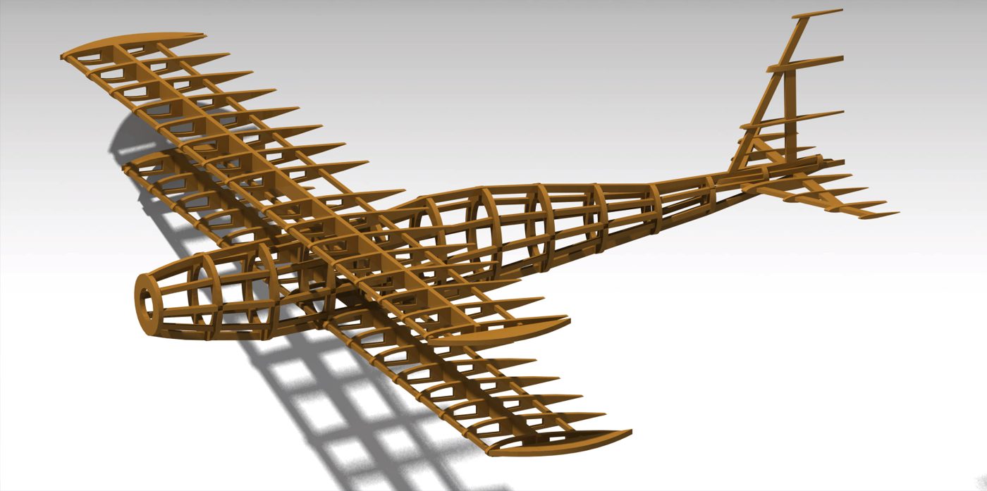
Fuselage. The barrel-shaped fuselage was rebuilt from a series of formers and stringers. The cockpit area includes a scale instrument panel and pilot seat, and the engine cowling, which houses the radial engine on the real aircraft, was modeled in detail with cooling vents and a circular front opening.
Tail. The control surfaces (ailerons, elevator and rudder) were not part of the manufacturing process. The horizontal and vertical stabilizers were designed.
All the parts were then assembled together in CATIA V5.
Simulation and Analysis
The XFLR5 analysis confirmed that the scale model should have satisfactory stability. We ran simulations at different angles of attack and sideslip angles to make sure the model would handle predictably in flight. One run at 10 m/s and 2 degrees angle of attack gave a lift coefficient of 0.5, a drag coefficient of 0.054 and an L/D of about 9.3. The plots below show the pressure distribution on the wings and tail, the drag polar, lift curve, stability curves, aerodynamic efficiency curve and normal force curve.
Manufacturing Process
The manufacturing combined traditional model aircraft building with digital fabrication.
CAD preparation. Every part was designed in CATIA and exported as a DXF file for the laser cutter. The parts were arranged on cutting sheets so that as little material as possible went to waste. The curved sections of the fuselage needed particular attention so that everything would still line up during assembly.
Laser cutting. Using the laser cutting facility in the manufacturing laboratory, we cut the fuselage formers and stringers, the wing ribs and spars, the tail surfaces, and the mounting plates and bracing components. The cutting was split into several sessions to stop the machine from overheating and to keep the cuts precise, and we kept adjusting focus so the cuts stayed clean in the different material thicknesses.
Assembly
Fuselage. The formers were lined up on a building board and joined with stringers to make the barrel shape, with extra reinforcement added at the high-stress points.
Wings. The ribs were threaded onto the main and rear spars and lined up carefully. The leading and trailing edges were added, followed by diagonal bracing between the ribs. Each wing was built flat on the building board to keep it straight.
Biplane structure. The lower wing was attached to the fuselage first, then the N-struts were installed and finally the upper wing. Getting every part aligned was critical for the correct stagger and gap between the wings.
Testing
The finished model went through tests of its structure and balance. Load tests were done on the wing structure and the landing gear to make sure they could take the stresses of flight and landing. The model was then balanced at the calculated CG position, with adjustments made where they were needed.
Conclusion
The 1:10 scale Grumman F3F model captures the distinctive design features and structural character of this historic aircraft. The biplane layout brought its own manufacturing challenges, mostly in keeping the wings and struts properly aligned. The finished model has good structural integrity and, according to the simulation results, should have stable flight characteristics.
The process mixed traditional model building with modern digital fabrication, which allowed precise parts while keeping the craftsmanship needed for a historical aircraft reproduction. The project improved our understanding of aircraft design, the structural side of biplane configurations and the manufacturing methods for complex aerodynamic structures.
References
- Naval History and Heritage Command, National Naval Aviation Museum. Grumman F3F-2. history.navy.mil
- Grumman F3F. Wikipedia. en.wikipedia.org/wiki/Grumman_F3F
- I. H. Abbott and A. E. von Doenhoff, Theory of Wing Sections, Including a Summary of Airfoil Data. Dover Publications, 1959.
- D. P. Raymer, Aircraft Design: A Conceptual Approach, 6th ed. American Institute of Aeronautics and Astronautics, 2018.
- A. Deperrois, XFLR5: analysis of foils and wings operating at low Reynolds numbers. xflr5.com
- Airfoil Tools, NACA 4-digit airfoil database. airfoiltools.com